AirPort Roaming Network Configuration
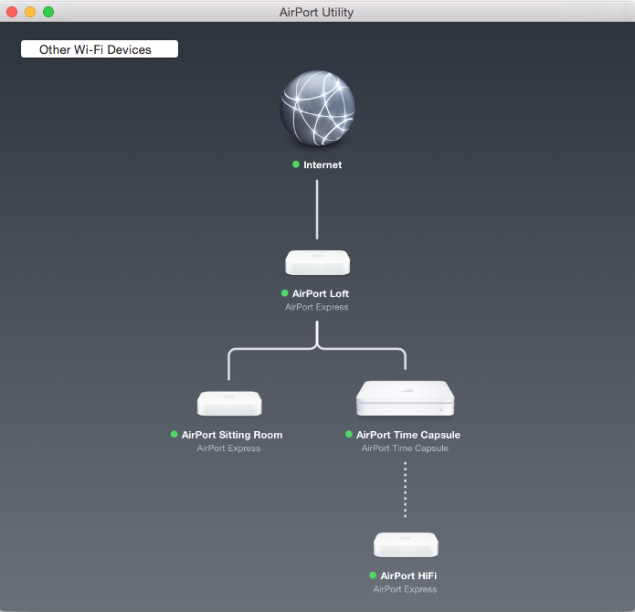
The above diagram shows a home Airport network with wired (RJ-45) Airports in the Sitting room, Reception (Time Capsule) and Study (Loft) and a wirelessly connected Airport in the Conservatory connected to a HiFi system using a audio mini-jack port. Due to the proximity of the Airport HiFi it wirelessly connects to the nearest AirPort Time Capsule in the Conservatory. The wired AirPorts are connected to the LAN using a straight Ethernet cable connected to the WAN ![]() port and nearest room RJ-45 wall port.
port and nearest room RJ-45 wall port.
The room RJ-45 wall ports are wired internally to an 8-port Gigabit switch in the loft. The loft router is represented by the Internet green dot in above diagram. The router LAN port connects directly to the loft switch and its ADSL port to the telco broadband telephone filter.
Airport Configuration
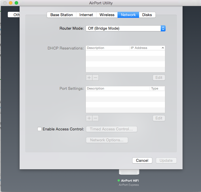
Airports are configured using the AirPort Utility application
All Base Station settings are configured with a unique name, .e.g “AirPort Sitting Room” and identical login passwords.
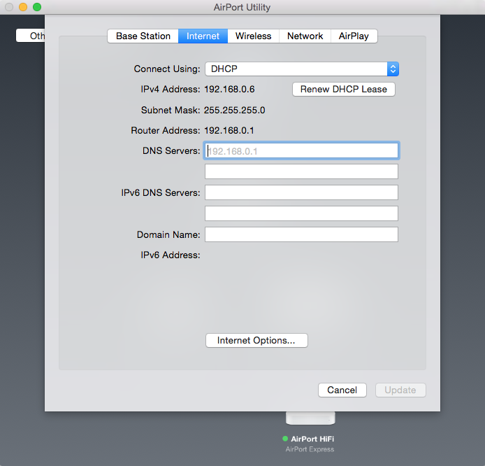
All Internet settings are configured to connect using “DHCP”. This means the AirPorts will automatically get their host, DNS and gateway IP addresses from a DHCP server. In this example it is the loft router.
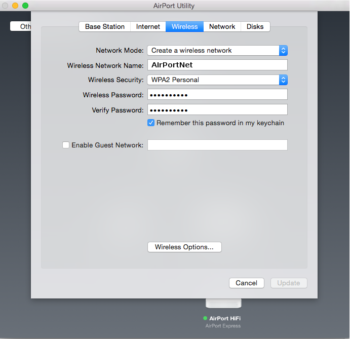
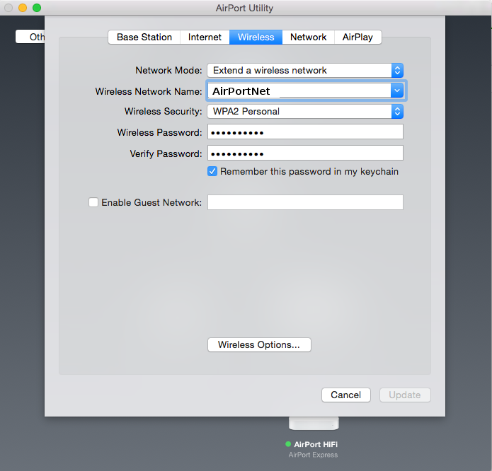
All Wireless settings are configured with an identical Network name (AirPortNet), Password and Security setting.
The wired AirPort Network Modes are set to “Create a wireless network”.
The wireless AirPort (AirPort HiFi) Network Mode is set to “Extend a wireless network”.
All Network settings are set to “Off (Bridge Mode)”
Airplay is disabled on all AirPorts except the conservatory Airport HiFi.